This is still a work in progress!
Introduction
In this post, I’m trying to put together some information that can be useful to a person trying to hack a car. It comes without the promise to be complete or correct. What follows is just a collection of questions I had while approaching this world and my attempt to answer said questions.
Where to start?
There are different ways to interface with a car that differs in complexity and cost. One simple way is using the OBD-II port, which is usually found in the car’s driver side.
What’s OBD?
OBD stands for on-board-diagnostic. It’s a general term that refers to the self-diagnostic and reporting capabilities of a vehicle.
There exist different standards related to OBD. The most common nowadays is ODB-II, for cars made from ~2000 onwards.
What’s OBD-II?
OBD-II is a group of ISO/SAE standards that define things like:
- the shape of a connector (sometimes referred to with the name of the standard, SAE J962)
- its pinout
- The format of the message exchanged
- common “trouble code”
- service IDs
I’ll refer to the latter 3 points as the “OBD-II protocol”.
What’s the OBD-II protocol?
As said, it’s a protocol made to access diagnostic information of a car.
It’s a straightforward protocol based on two key concepts:
- Service ID
- Protocol ID
Each service ID is associated with several protocol IDs, and each combination of service IDs and protocol IDs provides access to a piece of specific diagnostic information.
The protocol allows a device to make a query using a tuple of service ID and protocol ID (encoded in a way that is explained later). On the other side, an OBD-II aware ECU will respond to the query with the appropriate information.
Some service IDs/protocol IDs are fixed (and public) others are manufacturer specific.
Wikipedia contains a handy list of common service IDs/protocol IDs.
How data is transmitted over the OBD-II port?
While OBD-II specifies a common way to retrieve diagnostic information from the car, it provides different choices for the lowest level details of the communication, like what is the layer 1 to use to exchange these messages, but it obliges the manufacturers to make this detail public.
In practice, for cars made after 2006, chances are they are using CAN.
As for the pinout, OBD-II connectors have 16 pins: some of them are manufacturer-specific some of them are standard.

As for the standard pins:
- 2-9: PWM/VPW, Respectively, +/-
- 4-5: Chassis/signal ground
- 6-14: CAN+/CAN-
- 7-15: K/L Line
- 16: Vcc
Variable pulse width (VPW), Pulse width modulation (PWM), Keyword Protocol (K/L) are usually found on very old cars (with some exception, like general motors). As I said, CAN is the most common, hence you’ll end up using only 6-14 pins most of the time.
As for the manufacturer-specific pin, they are, well, manufacturer-specific. Not too much to say here except that sometimes connected pins can be found just by seeing the connector.
Here is an example of the OBD-II connector in a real car. It’s easy to spot which pins are wired and which are not:
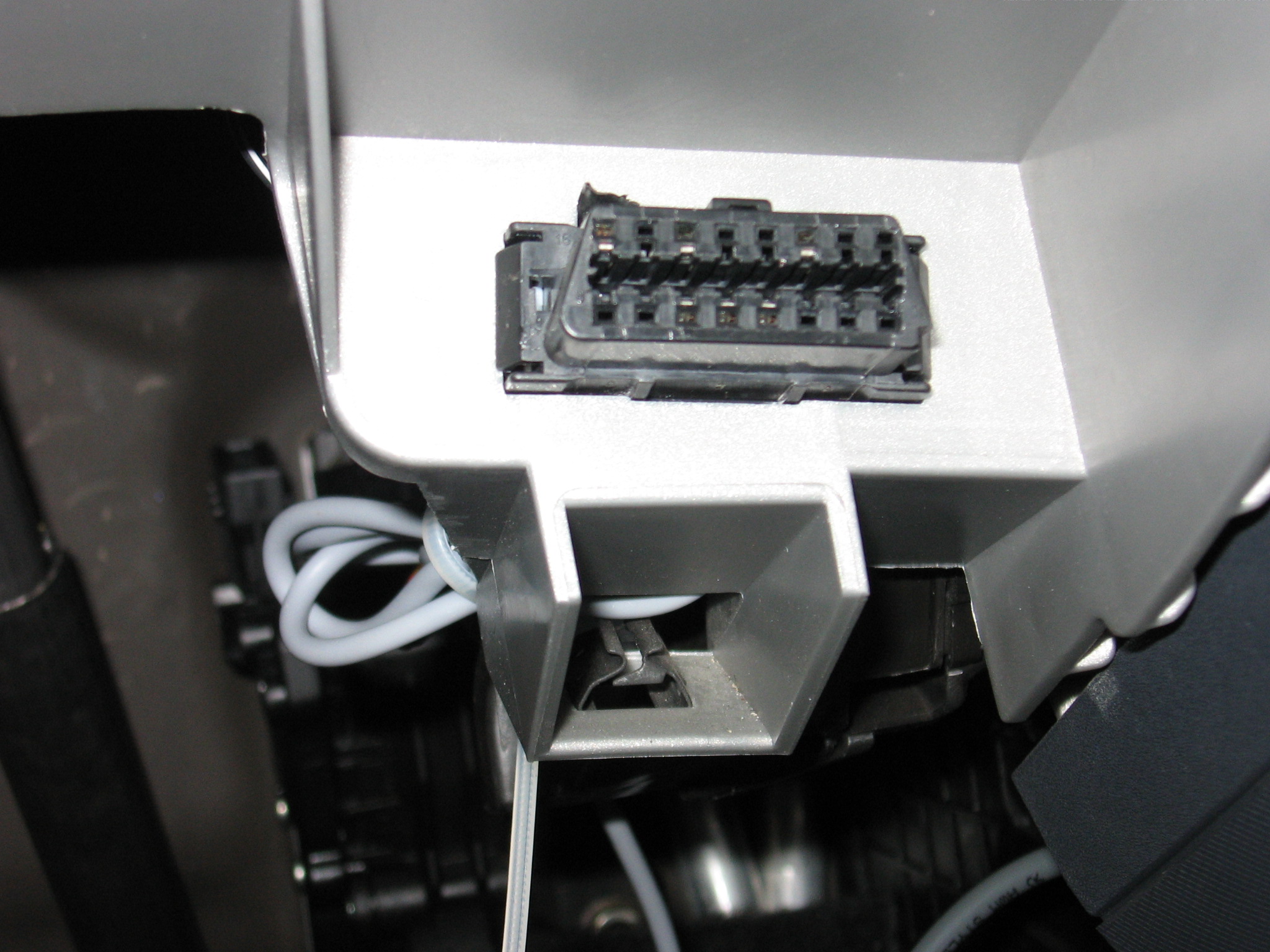
Understanding what’s going on these manufacturer-specific pins is, of course, another story. In some cases, a multimeter/oscilloscope can be useful (if you know what you are looking for); in other cases, you can find some leaked service manuals of the car online.
On these pins, you can find, for example, another CAN network.
What is CAN?
When we talk about CAN, we are talking about ISO 11898.
ISO 11898 is divided into ISO 11898-1 (data link layers), ISO 11898-2 (physical layer) and ISO 11898-3 (physical layer for fault-tolerant CAN).
CAN it’s a standard for serial communication made to be tolerant to noises. On its lowest level, it uses RS485, but while RS485 regards only the physical layer, CAN it’s specifying also the data link layer.
What follows is a summary of the key concept of CAN. They can be useful to understand how ECUs and devices communicate, but it’s not mandatory to understand those detail to hack a car, as some kind of adapter normally manages them (as explained below). Feel free to skip this part.
1. Physical Layer
As said, for the electrical part CAN is essentially RS485.
CAN uses 2 wires and differential signaling. This means the two signals present on the wires are complementary, e.g.: if the tension on the first wire drop of 2V, the tension on the second wire surge of 2V. This is shown to have a good rejection of noise.
2. Datalink, Collision, and priorities
Conflicts are managed by introducing the concept of “dominant” (== 0) and “recessive” (== 1) bits.
Recessive bits are not visible on the bus if some other device is transmitting a dominant bit at the same time. This can be useful both for collision detection and managing priorities.
Collision detection is done by probing the channel while transmitting. If the sender is sending a recessive bit but probe a dominant bit, he has the certainty that a collision occurred.
Other possible collisions go unnoticed.
These collisions are:
- 2 dominant bit sent at the same time
- 2 recessive bit sent at the same time
- sending a dominant bit while another device is sending a recessive bit
When a device notices a collision, it will stop the transmission.
Because of the structure of CAN messages, at the beginning of each message, there is the transmitter ID. From what was said, it can be inferred that the sender with a lower ID will have more priority on the bus, as they’ll have an occurrence of a dominant bit earlier in the ID.
3. Datalink, Frames
There are 4 kinds of frames specified by the CAN protocol:
- Data: Used to transmit data.
- Remote: Used to request data transmission to another node.
- Error: Used to signal an error.
- Overload: Used to delay a data or a remote frame.
The format of the telegram on the wire is always the same, regardless of the frame type:
| Name | Lenght | Description |
|---|---|---|
| Start | 1 | Start of the telegram |
| ID | 11 | Message ID |
| RTR | 1 | Request to transmit (dominant for data frames, recessive for remote frames) |
| IDE | 1 | Additional identification bit |
| R0 | 1 | Reserved |
| DLC | 4 | Lenght of the data field (bytes) |
| Data | 4-8 B | Data |
| CRC | 15 | |
| DCRC | 1 | Always a recessive bit |
| ACK | 1 | Recessive in the transmitter, dominant in receivers |
| DACK | 1 | ACK delimiter; Always a recessive bit |
| EOF | 7 | All recessive bits |
How CAN is used inside a car?
CAN buses are used to connect devices to ECUs and ECUs to other ECUs.
I guess it’s safe to say that most car has at least 2 different CAN networks: the first, slow and fault-tolerant, is for the “serious” and critical stuff. The second, faster, is for the infotainment-ish stuff.
- Example of 1st kind of messages: “Key is inserted”, “Immobilizer is off”
- Example of 2nd kind of messages: “Air-conditioning is ON”, “Radio is on 98.5MHz”
For cars that use CAN, At least one of the networks presents inside a car is exposed through an OBD-II connector using standard pins 6-14. The ECUs connected on these pins can handle the “OBD-II protocol”, as the whole purpose of the OBD-II port is to provide a common way to access the diagnostic of a car.
In some cases, even a second CAN bus is exposed using manufacturer-specific pins. The messages exchanged on this second network are highly dependent on the manufacturer.
How the OBD-II protocol is encoded in a CAN bus?
For cars that use CAN, every request for OBD information is made to the address 0x07DF. In the data field, the first byte identifies the service ID, the second byte identifies the protocol ID. That’s everything that is needed to make an OBD-II query.
Because there can exist multiple ECUs, the address 0x07DF act as a broadcast address. Every OBD-II aware ECUs will listen to this address and respond to the message using its ID.
The response length can vary depending on the information asked.
Which component to use for interfacing with a car?
Here we’re getting to the meat and potato of car-hacking. Different choices are depending on what goal you’re trying to achieve. I’ll explore some of them.
All-in-one OBD-II to USB/WiFi/Bluetooth adapter
These devices easily allow you to connect with an OBD-II port. At their core, they have an OBD-II to RS232 ICs and a WiFi/Bluetooth transceiver or a USB controller.
There exist many kinds of these devices, but most of them are based on ELM327 ICs. Even if there exists other OBD-II to RS232 ICs (like the STN1110, that seems to be also more hacker-friendly), ELM327 is the standard “de-facto” in this field. Other chips try to be compatible with the ELM327’s AT interface (see below), due to the numerous applications that are made for it.
ELM327 is a PIC microcontroller programmed in a certain way to provide a high-level interface to the OBD-II protocol. It supports every possible protocol specified by OBD-II standards while other ELM32x support only a specific subset.
Interacting with ELM327 is done via AT commands. The list of possible AT commands supported by ELM327 can be found on the manufacturer website.
Note that depending on the firmware installed on the device, it may or may not support all the AT commands. ELM Electronics provides a nice comparison of feature between versions.
This is a very important thing from the hacker perspective because some of these features are really important for your nasty hacking purposes (like sniffing).
Another important thing to consider is that there exists 2 variant of ELM327:
- Original EML327: this is the version made by ELM Electronic, which is an overall nice IC and a very simple way to interact with the OBD-II port.
- Crappy Chinese ELM327 clone: sometimes also found with the name “ELM327 mini”, it’s a crappy clone of the former adapter. From what it can be read from wikipedia, the first version of ELM327 does not come with copy protections and this made very simple for hackers to dump the firmware and re-use it on other hardware. It can be difficult to distinguish an original ELM327 from an ELM327 clone, here are some advice:
- If you’re going to buy one of them: as a rule of thumb, if it cost less than 10-15 bucks or it is called “ELM327 mini” don’t waste your money. Consider that, at the time of writing, the ELM327 price at retail is 21$ on the manufacturer website. Always read reviews of the product you’re going to buy or ask directly to the seller.
- If you already own one of them in a WiFi/Bluetooth variant: try using this app to see which capabilities the adapter has and don’t be fooled by the firmware version: it’s easy to find crappy Chinese stuff that claims to be “v2.3” but in fact they fail to provide all the capabilities required even by v1.0.
CAN to something adapters
ELM327 proved to be a very simple and cheap way to interact with an ECU. Unfortunately, ELM327 is meant to provide access to the diagnostics of the car, not to be a hacker-friendly device and it will mask most of the things that are happening on the lowest levels.
A better choice could be to use a CAN-to-* adapter, as it provides raw and unfiltered access to the bus.
For my experiments, I used an MCP2515 CAN to SPI adapter connected to a Raspberry.
RS485 adapters
While it is theoretically possible to use an RS485-to-something adapter, I don’t have any experience on this.
I can only guess that it should be way more difficult to make things work with said adapter, as a CAN-aware adapter is normally made by a transceiver and a controller. With an RS485 adapter, you get the transceiver (that handle most of the layer 1), but you don’t get the controller (that handle the layer 2 and part of the 1). Because of this, you’ll need extra software to manage things like bit-stuffing and dominant/recessive logic.